Panel Test

Since we now have a new CNC, we can now professionally mill and engrave the Mustang’s panels.

But of course we have to do some testruns to see how it works, and what settings to use.

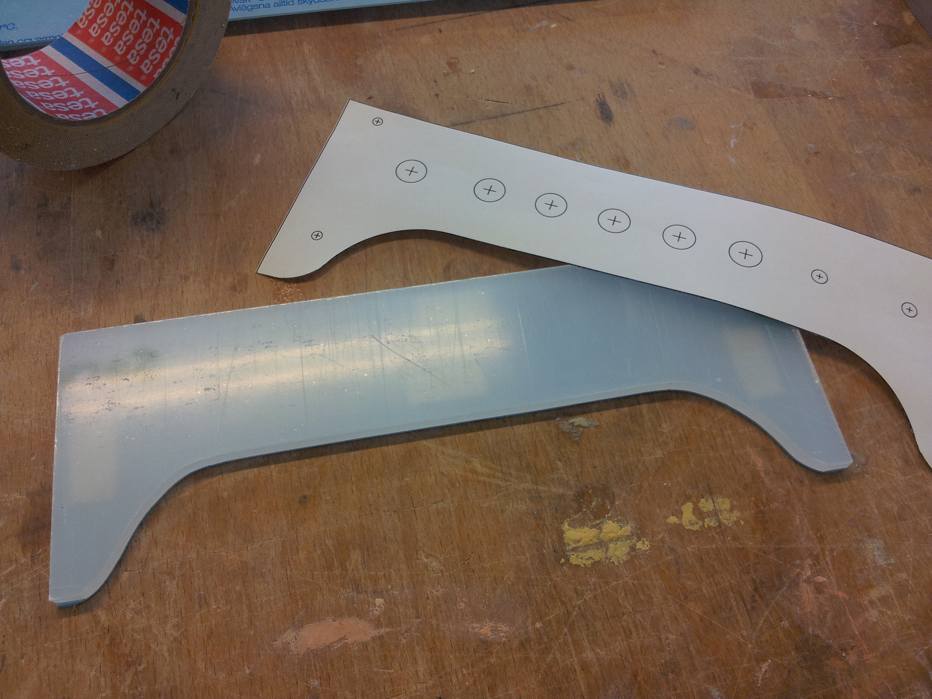
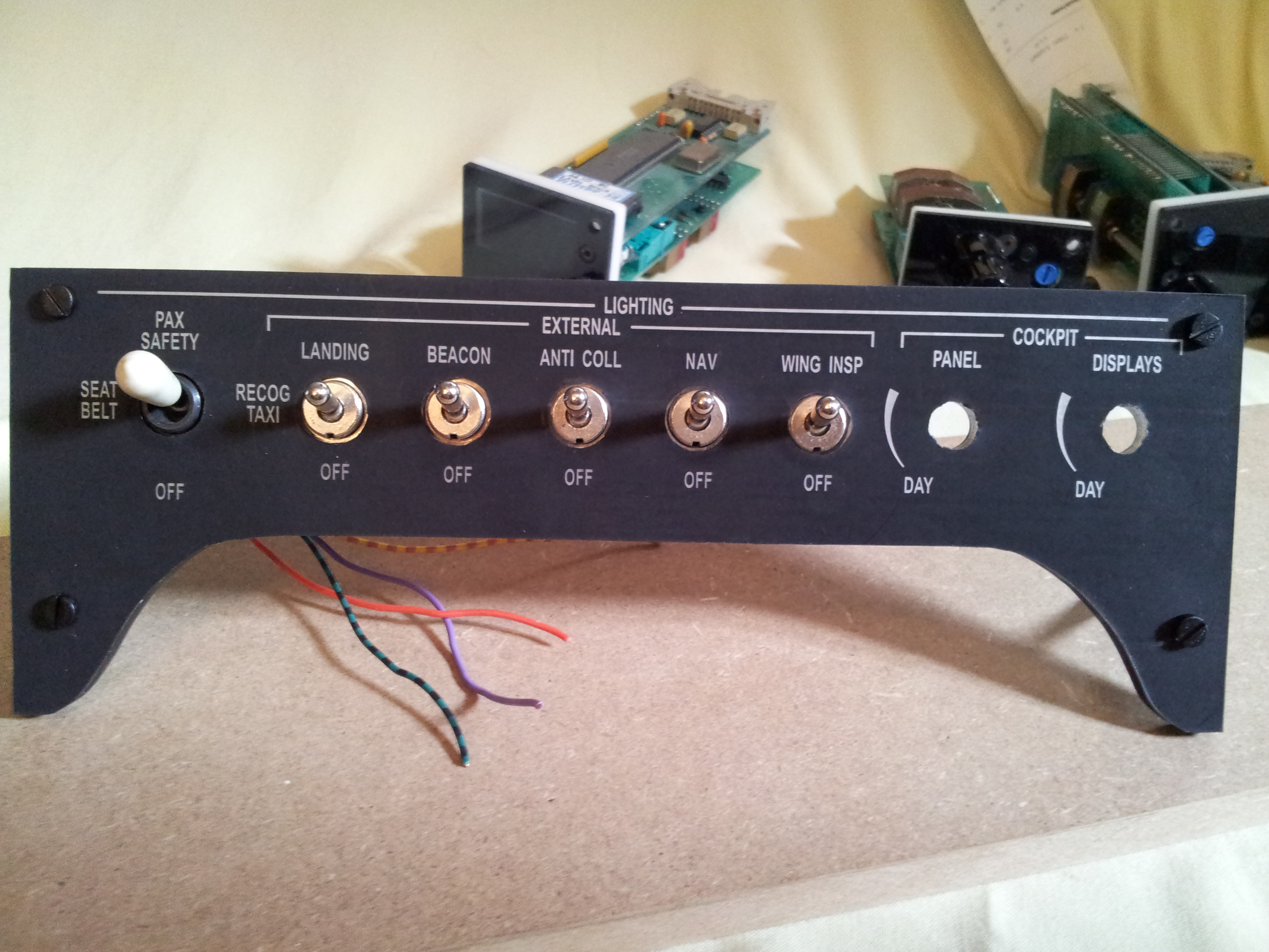
The following pictures show a testrun with the “oxygen control valve”-panel.

Obviously the engraving did not work perfectly, which is mainly caused by the wrong milling bit. I just ordered new bits so the next test should run smoothly.

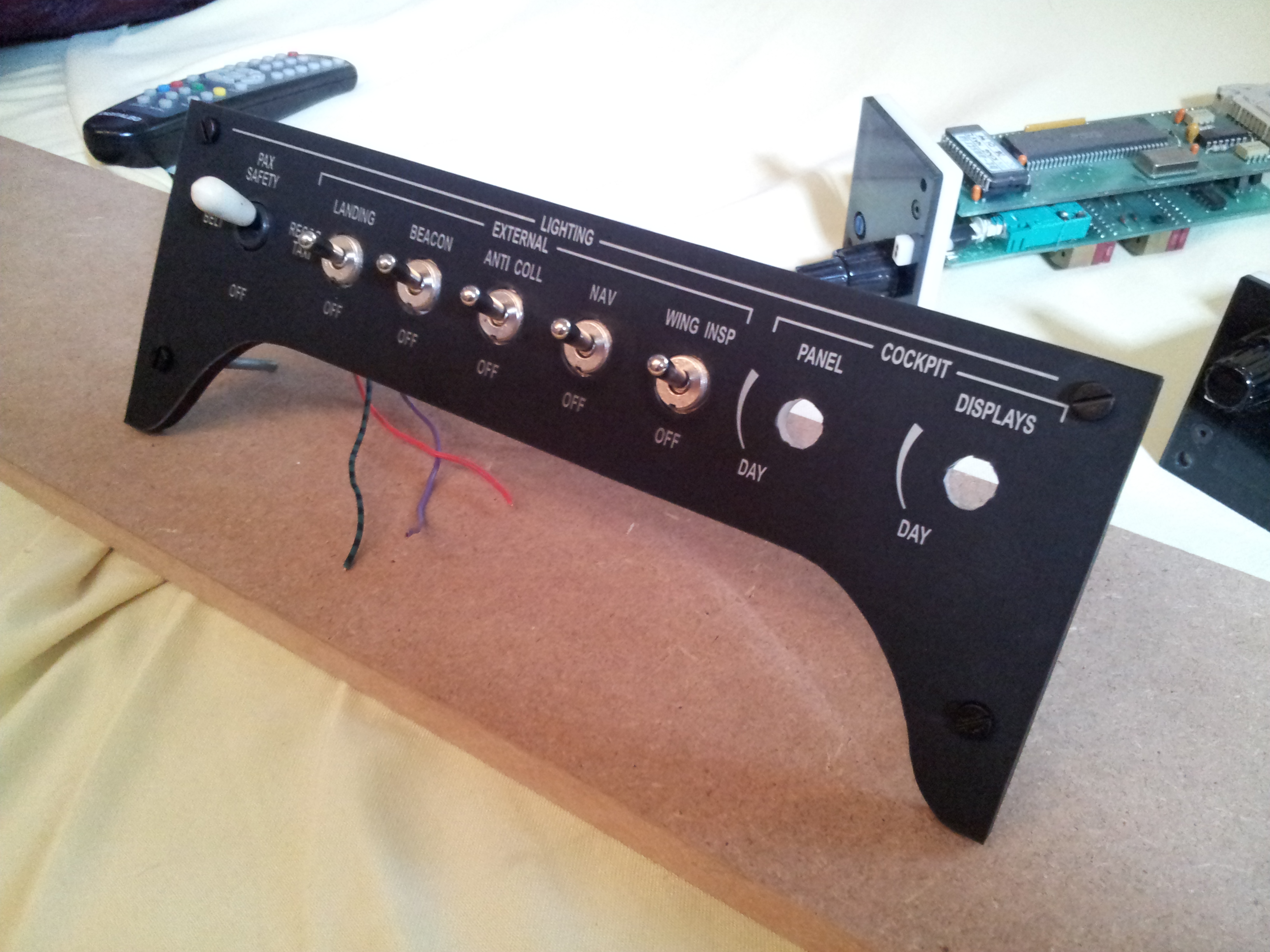
But on the other hand, the look of the panel is amazing, just look at the surface. It looks and feels amazing. And also the backlighting works as expected (if only the engraving was better… 😉 )


CNC’ed Rotary Knob

The first “real” CNC-job our new machine did,
was a model of the Cessna Citation Mustang rotary knob you’d find on the lighting panel or on the temperature panel. 

These knobs are obviously not available to buy, so we have to make our own. The plan is to make a mold of the model and cast it with epoxy resin to get exact replicas.

We probably have to make another model slightly bigger than the original, because the epoxy resin shrinks while hardening. 

new CNC

Since the last blog entry much has happened. We sold our first CNC machine in exchange for another, bigger one. Maybe you’ve already heard from it. It’s a shapeoko 2 from inventables. This amazing thing has everthing one could wish for. It’s driven by an arduino, therefore I can operate it with my MacBook which is an immense plus. The workspace is way bigger than our old one, measuring approximately 30x40cm. It’s a much sturdier machine made from special aluminium extrusions called “makerslides”. Thanks to those, one could expand the machine up to 1x1m workspace! Anyway, we’re looking forward to work with the machine, so stay tuned for the next posts. 🙂

NEW HARDWARE PART II

As I mentioned in my last post, we don’t only have a new PC,
but also something else.

That something is an awesome piece of technology 😉 A desktop-sized CNC machine!

We purchased the new MYDIYCNC kit. It has an unbeatable price, and as a plus it comes with a little box with which you can control the machine over USB.

The following video shows just how the CNC works. In that case it draws our logo onto a sheet of paper.

For more information on the CNC visit mydiycnc.com

Lights Panel

I proudly present: Our first panel! It’s not fully populated yet but soon it will be.

The panel consist of two layers of acrylic glass. The front plate has the labels printed on. The second one holds the switches and LED’s. The translucence helps spreading the light evenly.

When I’ve got the time I will be posting a tutorial on how we make those panels.

At this stage the labels are printed on. We hope to update the panels with engraved labels in the future. As the main goal right now is to complete the cockpit as fast and with little cost as possible the engraved panels are not that important.

Let’s move on to the pictures:

IMG_20130607_150545

Cut from Acrylic

IMG_20130609_171309

Two knobs on the right are still missing

IMG_20130609_171326


Encoder Testing

This weekend I tried to get an encoder to work properly. Luckily after a few attempts and some blind guessing I succeeded.

I’m using an additional card connected to the SIOC Mastercard that reads the encoder’s inputs.

I programmed this particular encoder to set the Heading value. You can see the encoder in action in the video below. The heading bug is following the inputs nicely.

I’m just holding the encoder weirdly because I’m filming with my other hand…obviously 😉

::

Little Preview

Here is a little preview of the sim will look when finished.

It’s been drawn in Trimble SketchUp with help of the original Citation Mustang measurements. It’s a simplified design to reduce costs and building complexity. We will for example use a single 20″ monitor for only two Garmin G1000 screens (in the Mustang there’s one Pilot PFD, a big 15″ MFD and a second PFD for the F.O.)

But we want to recreate every switch and button to give us the full “Mustang-experience”.

Here are the pics:

Flusi_12_2 Flusi_12

Attitude Indicator Testing

I recently came across an old Cessna 172 (?) instrument panel

which was used as a training simulator.

It has a complex interfacing but was not intended for the use with FSX. However its instruments are already prepped with servos and/or stepper motors. Thus making it great for adapting it for our purposes.

The Mustang has, although equipped with the Garmin G1000 flightdeck, three standby instruments: Speed indicator; Attitude indicator and the vertical speed indicator.

In this case I disassembled the attitude indicator unit and found that we don’t need that fancy electrical stuff hidden inside. I disconnected all the unneeded cables and boards and remained with just the mechanics and two servo motors attached to it. I connected the servo cables to our servo driving card and programmed a short script in SIOC (our interfacing language).

A short video in which I am testing the response of the indicator: